Friday, 4 October 2013

LAB 1

JM 507
CONTROL SYSTEM

Experiment 1 : Level Control Demonstration Panel

Control technology is now an integral part of nearly all areas of engineering.Accordingly, a description of its basic principles is a standard feature of technical training programs.

The demonstration model of the RT-6x4 series from G.U.N.T make it possible to ascertain relationship between control parameters in practical experiments and demonstrate these relationships so that they are clear and easily memorizable.

Every model comparises a fully functional system of process with it own control circuit.An extensive use of modern industrial component makes the model are realistic as possible.students thus not only obtain knowledge of basic control principles  but also an overview of the control element's design, functionality and application.

The models have a desktop design and require very little maintenance.They are ideal as training aids for laboratory experiments at technical college and universities and intended exclusively for educational purposes.

1.Devices description
  • The RT 614 demonstration model is a desktop device to control filling levels.
  • Water is used as the operating medium here.Filling levels are controlled by an electronic industrial unit which can be configured as a P, PI, or PID controller.
  • Experiments with demonstration model involve modification and adaptation to system control parameters.

2.Device layout

  • The RT614 demonstration model for filling level control has following layout :


  1. Filling-level cylinder
  2. Filling-level sensor
  3. Drain cock with scale
  4. Water tank
  5. Pump
  6. Electric proportional wave
  7. Pump switch
  8. Jack for the Y control signal
  9. Switch for internal/external changeover of the Y control signal
  10. Controller
  11. Jacks for the X signal from the filling-level sensor

3.Process scheme


  1. Filling-level cylinder
  2. Filling-level sensor
  3. Controller
  4. Control valve
  5. Pump
  6. Drain cock
  7. Water tank

4.The controller

  • The digital universal controller is equipped with a microprocessor with digitally process input signals and converts them back to analog variable prior to output.
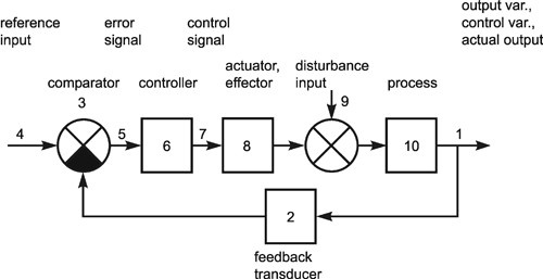
5.Question
  • Daw block diagram for the control system?
      

E = U - Y
  • This relationship is for the summer/subtractor (shown with a green circle)
W = KE
  • This shows how W - the control effort that drives the system being controlled, G - is related to the error.  The controller is probably an amplifier - probably a power amplifier - that provides an output to drive the plant, G.
Y = GW
  • This shows how the output, Y, is related to the control effort that drives the plant (system being controlled ) with a transfer function, G.
  • Note that Y = GW
  • Note that W = KE, and use that in the equation for Y.  That gives you:
    • Y = GW = GKE
  • Note that the error is given by E = U = Y, and use that in the equation for Y.
    • Y = GW = G(s)KE = GK[U = Y]
  • Now, solve for Y, and you get:
    • Y = UKG/[1 + KG]

Tuesday, 13 August 2013

soalan control system


soalan control system

1)   A Proportional Controller is used for controlling temperature in melting process. Temperature set point is750°C and temperature measuring tool range is 0 - 1000°C .  Proportional space is set  at 15%.  Pressure output range from controller is 20 –100 kN/m2 and pressure output rises when temperature increases.  If pressure output is set at 60 kN/m2 for temperature set point, find


 i)          Temperature for pressure output at 20 kN/m2

                 Pb = 15 %                                                                Kp = 100
             Pb(0) = 50%                                                                           50
                   P  = 20kN/m2                                                       
                                                                                                  Kp = 100 
                                                                                                             15 
           
      E = Sp – Mv  (100)
              Range                                                                                  P(t) = KpEp + P(0)

          -7.5= 750 - Mv      (100)                                                          0 = 100   Ep + 50
                    1000 -0                                                                                  15

                   Mv = 825 0 C                                                                    100Ep = 50
                                                                                                               15
                                                                                                         Ep =  50   (15)
                                                                                                                   100
                                                                                                          Ep = -7.5


            ii)         Temperature for pressure output at  100kN/m2    

                   P = 100 kN/m2                                 E= Sp – Mv  (100)
                   P = 100%                                          Range          
                   Kp = 100                                     7.5 = 750 –Mv   (100)
                             15                                                 1000

                    P(t) = KpEp + P(0)                    Mv =  (7.5 x 1000) - 750

                    100 = 100 Ep + 50                       Mv = -67500C  #
                               15
                  100 Ep = 100- 50
                   15
                         Ep= 50    (15)
                                 100
                    
                         Ep = 7.5


2)  In a process, a Proportional Controller is used to control the liquid level in the boiler. The   
          level is set at 8 meters and the level range is 1 to 14 meters. Proportional band is at 
          20%.  The output current has a range of  5 – 20mA. Determine:-


i.                    The output level when current is 5 mA.


Ep =                       Sp – Mv    ( 100 )                  P(t) = KpEp + P(0)
                               range
                     Ep =  8 – 10  x 100                         P = 5(-15.38) + 50
                                14 – 1
                         Ep = -15.38                                 p =   -26.9 %

                          = current – min.     x 100
                              Max   -  min

                           -26.9 = Mv – 1 x 100
                                       14 – 1
                             -26.9(13)  = Mv – 1
                   100       
                                Mv = - 2.5 


ii.                  The output current at a level of 10 meters.


        controller output = current – Min out    x 100
                                             max out – min out
                                                     = 10 – 5  x 100
                                            20 – 5
                                                     =  5   x  20%
                                            15
                                                   =  7 meters


            3)    An air to open valve on the inflow controls level in a tank. When the process is at the set point the valve opening is 50%. An increase in outflow results in the valve  opening increasing to a new steady state value of 80%. What is the resulting offset if the controller PB is:  


                       i)                    80%


                        Pb =              100            
                              proportional gain, Kp

                         80 =  100
                                 Kp
                        Kp =  100
                                  80


                      ii)                   40%.
                                                                                                                      
                      Pb =               100             
                               Proportional gain, Kp

                      40 = 100
                              Kp

                      Kp = 100
                               40


4.   A temperature controller has the following characteristic curve below:


The controller has a range of 100 0C to 400 0C. The setpoint is 250 0C. Calculate:


   i.            The controller Proportional Band

Positive error band                                                               negative error band
=        3 0C                    x 100                                                     =       - 50C     
    (400 – 100)0C                                                                          (400 – 100)0C       
= 1.7 %                                                                                         = - 1.7 %
    
= 1.7 – ( - 1.7 )
=  3.4 %

                                              ii.            The controller Proportional Gain

                       Proportional band, Pb  =            100                
                                       Proportional gain, Kp
                             Pb = 100
                                      Kp
                            
                             3.4 = 100
                                       Kp
                             Kp = 100
                                      3.4
                             Kp = 29. 41


Tuesday, 30 July 2013

FORMULA

1) CONTROLLER OUTPUT IN PERCENT.

Controller output % = current output -  minimum output
                                                  ----------------------------------------------         X 100
                                        maximum output - minimum output


2)MEASURE VALUE AS PERCENTAGE

Measure value in % =  MV - minimum MV
                                                      --------------------------------    X 100
                                         max MV - minimum MV


3)SET POINT AS PERCENTAGE VALUE

Set point % =     SP - min value
                                               ----------------------------     X 100
                               max value - min value


4)ERROR AS PERCENTAGE VALUE

Error point % =            % SP X MV
                                                       -----------------------------   X 100
                                         max value - min value


5)PROPORTIONAL BAND

Proportional band , PB =             100
                                           ---------------------
                                           proportional gain , KP

                                  PB = 100
                                           ------
                                            KP


6)CONTROLLER OUTPUT

 P = Kp*Ep X P(0)


7)POSITIVE ERROR BAND

Positive error band =    max permissible positive error
                                                         -------------------------------           X 100
                                     temp range


8)NEGATIVE ERROR BAND

 Negative error band = max permissible negative error
                                                         -------------------------------                X  100
                                        temp range


9)PROPORTIONAL CONTROLLER

E = SP - MV

P(i) = KP*EP + P(0)

Wednesday, 17 July 2013

Examples of Modern Control Systems
A manual control system for regulating the level of fluid in a tank by adjusting the output valve.The operators view the level of fluid through a port in the side of the tank. 


A three -axis control system for inspecting individual semiconductor wafer with a highly sensitive camera.


Coordinated control system for a boiler generator. 


SYSTEM CONTROL DESIGN.

The control system design process.


(a) open-loop (without feedback) control.
(b) closed-loop control of blood glucose..


Saturday, 29 June 2013

OPEN AND CLOSE LOOP


Open-Loop Control Systems.
Those systems in which the output has noeffect on the control action are called open-loop control systems


Closed-Loop Control Systems.
Feedback control systems are often referred to as closed-loop control systems.In a closed-loop control system the actuating error signal, which is the difference between the input signal and the feedback signal(which may be the output signal itself or a function of the output signal and its derivatives and/or integrals), is fed to the controller so as to reduce the error and bring the output of the system to a desired value.

CLOSED-LOOP CONTROL SYSTEM
Advantages of Open Loop

Simple construction and ease of maintenance.
  • Less expensive than a corresponding closed-loop system.
  • There is no stability problem.
  • Convenient when output is hard to measure or measuring the output precisely is economically not feasible.

Disadvantages of Open Loop
  • Disturbances and changes in calibration cause errors,and the output may be different from what is desired.
  • To maintain the required quality in the output,recalibration is necessary from time to time.
  • They are less accurate.
  • If external disturbances are present, output differs significantly from the desired value.


TERMS USED IN CONTROL PROCESS
  • Variable Process - proses pembolehubah
  • Servo Controlled -pengawal serbo
  • Feedback             -suap balik
  • Process                -proses
  • Set Point              -titik mula
  • Error                    -ralat
  • Controller            -pengawal
  • Measurement      -pengukuran